Automotive manufacturers are investing in increasingly sophisticated digital capabilities, from real-time production monitoring and predictive maintenance to automated quality inspection, production traceability, and AI-assisted decision-making. Yet, despite the growing availability of connected equipment and enterprise software, many factories continue to struggle with a fundamental architectural problem: operational data remains fragmented across systems that were designed to work independently.
A manufacturing plant may rely on programmable logic controllers (PLCs), supervisory control and data acquisition (SCADA) systems, manufacturing execution systems (MES), enterprise resource planning (ERP) platforms, quality management applications, and cloud-based analytics tools, each of which generates or consumes information according to its own data structures, communication protocols, and operational requirements. As new applications are introduced, engineering teams frequently build additional interfaces to connect them to existing systems, creating a network of dependencies that becomes progressively harder to understand, maintain, and extend.
This challenge is particularly significant in automotive manufacturing, where production lines involve tightly coordinated processes, complex bills of materials, numerous suppliers, strict quality requirements, and high expectations for traceability. A change to a production process, equipment configuration, or quality-control workflow may require information to move across several systems, and the value of that information depends not only on whether it can be transmitted, but also on whether every receiving application can interpret it correctly.
A unified namespace (UNS) offers a different approach to this problem by establishing a shared, logically organized data layer through which systems can publish and consume information without requiring a dedicated connection to every other application. Rather than treating integration as a growing collection of bilateral interfaces, manufacturers can build around a common information space in which data is structured according to consistent business and operational context.
The objective is not simply to connect more machines or collect more data. It is to establish an architecture in which information can be reused across manufacturing applications, new digital capabilities can be introduced with less integration effort, and the factory’s data infrastructure can evolve without requiring extensive redesign every time another system is added.
1. What Is a Unified Namespace in Manufacturing?
A unified namespace is a shared, logically structured representation of operational information that allows industrial systems to publish, discover, and consume data through a consistent information model. In a typical implementation, systems communicate through a message broker using a publish/subscribe pattern, with topics organized according to a predefined namespace structure and payloads carrying the relevant data and context.
In a conventional integration model, an application may need to communicate directly with several other applications to exchange production status, machine measurements, order information, or quality results. A UNS changes this relationship by allowing a system to publish information once to a shared data layer, where authorized consumers can subscribe to the information they need.
For example, a machine controller could publish its operating status and production measurements to a topic representing a specific factory, production line, and machine. A monitoring application could subscribe to that information to display operational conditions, while an analytics service could consume the same stream to identify performance trends. A maintenance application might use relevant status changes to support equipment diagnostics, without requiring the machine controller to maintain a separate interface for every consumer.
The namespace therefore provides a common way to organize and locate information, while the messaging infrastructure distributes that information to the systems that need it. The combination can make data integration more modular, although the quality of the outcome depends on how consistently the namespace, data structures, and ownership rules are designed and maintained.
What a unified namespace is not
A UNS is not simply a message broker, a centralized database, or a replacement for every existing manufacturing application. A broker provides the communication mechanism, whereas the namespace defines how information is organized and identified; neither, by itself, guarantees that the underlying data is semantically consistent or operationally reliable.
Likewise, a UNS does not eliminate the need for MES, ERP, SCADA, historians, or specialized industrial applications. These systems continue to perform their respective functions, including production execution, enterprise planning, supervisory control, and historical data storage. The unified data layer provides a structured means of sharing relevant information between them.
Nor should a UNS be interpreted as requiring all data to be copied into one physical repository. Depending on the architecture, information may be distributed through event streams, retained in historical stores, processed at the edge, or made available through cloud platforms. The unification is primarily logical: systems share a consistent way to publish, identify, and interpret information, even when the underlying infrastructure is distributed.
Finally, adopting a UNS does not automatically resolve poor data quality. If different machines use inconsistent units, if production orders have conflicting identifiers, or if applications disagree about the meaning of a status code, the shared namespace can distribute those inconsistencies more efficiently without correcting them. A successful implementation must therefore combine connectivity with information modeling, governance, and clear operational ownership.
2. Why Point-to-Point Integration Becomes Difficult to Scale
Point-to-point integration remains a practical choice when a factory needs to connect a small number of systems with clearly defined responsibilities. A direct interface can be relatively straightforward to implement, particularly when the integration involves a limited data exchange and the requirements are unlikely to change significantly.
The difficulty emerges as the number of systems grows. Each new application may need to obtain information from several existing systems, and each connection can introduce its own data mapping, authentication mechanism, error-handling logic, monitoring requirements, and maintenance responsibilities. Over time, the integration architecture becomes dependent on a growing number of individually managed relationships.
Consider a simplified manufacturing environment in which eight systems exchange information directly with one another. If every system requires a dedicated bidirectional connection with every other system, the number of potential pairwise connections is N(N−1)/2. For eight systems, this produces 28 unique connections. If the environment expands to 15 systems, the number increases to 105. These figures represent a fully interconnected theoretical model rather than a prediction of the exact number of interfaces in every factory, but they illustrate why integration complexity can grow rapidly when systems are connected through individual relationships.
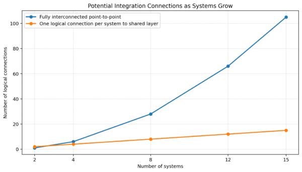
Figure 1. Illustrative comparison of fully interconnected point-to-point connections and one logical connection per system to a shared layer.
The operational burden extends beyond the number of connections themselves. When an application changes its data format, an interface is upgraded, or a new production line is introduced, engineers must determine which downstream consumers may be affected and whether the changes require coordinated updates. Where documentation is incomplete or integration logic is distributed across multiple applications, even a relatively small modification can require substantial investigation and regression testing.
This creates a form of architectural coupling in which the cost of future development is influenced by the integration decisions made during earlier projects. A new quality-inspection system, for instance, may need machine status from the shop floor, production-order information from MES, and historical defect records from a separate quality platform. If these relationships are implemented as bespoke interfaces, the new application adds to the factory’s existing maintenance burden and may create further dependencies when its own data is required elsewhere.
A unified namespace manufacturing architecture addresses this problem by changing the pattern of interaction. Instead of requiring each new application to establish multiple independent connections, systems publish and consume information through a shared layer. This does not remove the need for integration work, but it can reduce the number of bespoke relationships that must be designed, tested, and maintained as the manufacturing environment expands.
3. How a Unified Data Layer Manufacturing Architecture Works
A well-designed unified data layer manufacturing architecture combines several components that serve different purposes: data producers generate operational information, edge infrastructure collects and contextualizes it, a messaging layer distributes it, and consumer applications use it for monitoring, execution, analytics, and decision-making.
The architecture is most effective when these components operate according to a consistent information model rather than merely forwarding raw machine signals between systems.
3.1 Data producers: Connecting machines and enterprise systems
Data producers include industrial equipment and software applications that generate information relevant to manufacturing operations. At the shop-floor level, these may include PLCs, robot controllers, machine vision systems, sensors, and SCADA platforms. At higher levels, MES, ERP, quality management systems, maintenance applications, and planning tools can publish production-related information.
Because these systems differ in their communication capabilities, a UNS implementation may require protocol adapters, industrial gateways, or integration services to translate existing interfaces into a common messaging and data structure.
For example, a legacy machine may expose measurements through an industrial protocol, while an MES application may provide production-order information through an API or database interface. Both can contribute to the shared namespace, provided that their information is mapped to a defined model and that the transformation preserves the original meaning of the data.
The integration layer should also distinguish between data acquisition and data interpretation. Reading a machine register successfully does not necessarily establish what the value represents, which unit it uses, whether the value is current, or which production asset it belongs to. These details must be defined before the information can be used reliably by other applications.
3.2 The messaging layer: Publish/subscribe instead of bilateral connections
A message broker provides the communication mechanism through which producers publish information and consumers subscribe to relevant topics. MQTT is commonly used in industrial IoT architectures because its lightweight publish/subscribe model supports communication between distributed devices and applications without requiring each producer to know the identity of every consumer.
Under this approach, a machine publishes a status update to a designated topic, while any authorized application interested in that status can subscribe to the corresponding topic. If a new application is introduced later, it can consume the same information through the messaging layer rather than requiring changes to the original producer’s integration logic.
However, a broker does not automatically provide a unified data model, ensure end-to-end delivery, or make every message meaningful to every consumer. Topic conventions, payload schemas, quality indicators, security controls, message-retention policies, and operational monitoring must be designed as part of the overall architecture.
The implementation must also account for the distinction between event-driven messages and retained state. A message announcing that a machine has entered a fault condition describes an event at a particular point in time, whereas a retained representation of the machine’s current operating state helps a newly connected consumer understand the latest known condition. Both patterns can be valuable, but they serve different purposes and should not be treated as interchangeable.
3.3 Edge computing: Preserving operational responsiveness
In automotive manufacturing, many decisions must be made close to the equipment because network latency, connectivity interruptions, or remote processing delays may be unacceptable for certain control and safety functions. Edge computing allows data acquisition, protocol translation, filtering, local processing, and selected analytics to take place near the production environment.
A practical architecture can therefore separate time-critical machine control from higher-level data distribution. PLCs and dedicated control systems continue to execute deterministic control logic, while edge gateways collect relevant information and publish it to the unified namespace. This separation helps prevent enterprise analytics or cloud connectivity from becoming an unnecessary dependency for core machine-control functions.
Edge processing can also reduce the amount of information sent upstream. Rather than transmitting every high-frequency measurement continuously, a gateway may publish changes in operating state, selected aggregates, threshold violations, or events that are meaningful to downstream applications, provided that the filtering strategy preserves the information needed for traceability and analysis.
The appropriate balance depends on the use case. Predictive maintenance may require historical signal detail and sufficiently frequent measurements, whereas a production dashboard may need only the current state and selected performance indicators. Designing the edge layer around these distinct requirements helps avoid both excessive data transmission and the loss of information that later analysis may need.
3.4 Cloud platforms: Extending access to analytics and enterprise applications
Cloud infrastructure can extend the value of the unified data layer by providing scalable storage, cross-site analytics, model development, enterprise reporting, and integration with business applications. Where multiple factories operate under a shared information model, selected data can be made available for comparison across plants, supporting analysis of recurring downtime patterns, production performance, quality outcomes, and asset utilization.
Nevertheless, cloud integration should not be interpreted as a requirement to send every operational signal outside the plant. Data residency, cybersecurity policies, bandwidth limitations, latency requirements, and business confidentiality may dictate that certain information remains on-site or is shared only in aggregated or controlled form.
A hybrid edge-to-cloud design allows manufacturers to determine which information must remain close to production, which data should be retained locally, and which information can be made available to enterprise or cloud applications. This makes the architecture more adaptable to different plant conditions while preserving a consistent approach to information organization.
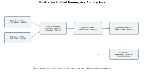
Figure 2. Illustrative UNS architecture showing shop-floor and enterprise producers, edge integration, messaging, namespace organization, and consumers.
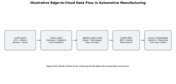
Figure 3. Illustrative edge-to-cloud flow; time-critical control remains local while governed data is shared with authorized consumers.
4. Designing a Manufacturing Data Model That Applications Can Understand
The namespace structure determines where information can be found, but the manufacturing data model determines what that information means. This distinction is critical because a shared topic hierarchy cannot guarantee interoperability when different applications interpret the same field differently.
A robust manufacturing data model should define common entities, their relationships, their identifiers, and the attributes needed to describe them consistently across systems. In automotive manufacturing, four useful starting points are assets, production orders, parts, and events.
4.1 Assets: Establishing a consistent equipment identity
An asset model describes the physical or logical resources involved in production, including factories, production areas, lines, workstations, machines, robots, and relevant subcomponents. The model should provide stable identifiers and establish parent-child relationships so that information can be associated with the correct equipment and location.
Enterprise\n└── Plant\n └── ProductionArea\n └── Line\n └── Workstation\n └── Machine
This structure is illustrative rather than mandatory; manufacturers should adapt it to their production topology and operational requirements. The essential principle is that equipment identifiers and relationships must remain consistent even when physical assets are moved, renamed, replaced, or represented differently in legacy applications.
Where relevant, the asset model can align with established industrial concepts, including the equipment hierarchy and operational definitions described in ISA-95-related models. The aim is not to impose a standard hierarchy without considering local realities, but to use recognizable industrial concepts to reduce ambiguity between engineering, operations, and software teams.
4.2 Production orders: Connecting machine activity to manufacturing intent
Asset data explains where an activity occurs, but production-order information helps explain why it occurs and which manufacturing objective it serves. A useful model should define how orders, operations, work instructions, batches, and production runs relate to equipment and timestamps.
For example, a machine may report that it has completed a cycle, but that event becomes significantly more useful when it can be associated with the relevant production order, operation, part, and work shift. This contextual relationship enables downstream applications to distinguish production output for different orders and investigate quality or performance issues with greater precision.
The model must also account for changes in order status and execution context. A production order may be released, started, paused, completed, or cancelled, and applications must have a consistent understanding of these states and the rules governing transitions between them. Without such definitions, two connected systems may exchange the same status value but reach different conclusions about the actual production situation.
4.3 Parts and product identity: Supporting traceability
Automotive production involves a broad range of product identifiers, including part numbers, serial numbers, component identifiers, variants, and supplier-related references. A unified data layer should define how these identifiers are represented and related to the relevant production activities, rather than assuming that one identifier can serve every purpose.
For instance, a part number may identify a product type, while a serial number identifies an individual manufactured unit. A batch or lot identifier may group a set of components or materials, and a vehicle identification number may represent a completed vehicle. These identifiers should be linked according to explicit rules so that quality records, inspection results, machine events, and material-consumption records can be traced to the correct product or production context.
This is particularly important when manufacturers need to investigate a quality issue across multiple production stages. A common data model can make it easier to correlate the affected product, the components used, the equipment involved, and the conditions recorded during production, although complete traceability still depends on capturing the required data at the relevant process steps.
4.4 Events: Preserving the context of operational changes
Events represent occurrences that matter to production, such as a machine entering a fault state, a cycle completing, an inspection failing, or an order changing status. A well-defined event model should identify the event type, the relevant asset or product, the event time, the source, and any additional attributes needed to interpret the occurrence.
A typical event payload might contain:
{\n “eventType”: “MachineStateChanged”,\n “assetId”: “Plant01.Line02.Machine05”,\n “timestamp”: “2026-10-28T08:15:30Z”,\n “state”: “Stopped”,\n “reasonCode”: “MaterialUnavailable”,\n “source”: “EdgeGateway01″\n}
This is an illustrative example, not a prescribed industrial standard. A production implementation would need to define schema validation, timestamp conventions, quality indicators, versioning, and the meaning of each field.
Event design should also distinguish the time at which an event occurred from the time at which it was received or processed. In distributed manufacturing environments, messages may be delayed or arrive out of order, and the difference between event time and processing time can affect the interpretation of production sequences, downtime calculations, and traceability records.
5. Namespace Design: Turning Data Into a Consistent Information Structure
A namespace should reflect the way the organization understands its production environment, allowing applications and engineers to identify information without relying on undocumented naming conventions or application-specific mappings. Poorly designed topic hierarchies can recreate the same fragmentation that the UNS is intended to address, particularly when different plants or engineering teams adopt incompatible structures.
A representative topic structure could be:
Enterprise/\n└── Plant01/\n └── Production/\n └── Line02/\n └── Machine05/\n ├── State\n ├── Metrics\n ├── Events\n └── Diagnostics
This structure separates information by enterprise context, production location, and equipment identity, while grouping related information by its operational purpose. The exact topic hierarchy should be chosen according to the organization’s data model and messaging requirements rather than copied mechanically from an example.
- Consistency across plants: Equivalent assets and processes should use comparable naming and modeling rules across sites, even when local equipment and production layouts differ. This supports reusable applications and cross-site analysis.
- Stable identifiers: Topic names should not depend unnecessarily on temporary conditions, informal equipment nicknames, or values that frequently change. Where asset relationships change, the architecture should define how identifiers and references are maintained.
- Clear separation of data types: Current state, measurements, events, commands, and configuration information may require different handling and permissions. Distinguishing these categories makes the information model easier to understand and helps prevent inappropriate access or interpretation.
- Version management: As payload schemas and business definitions evolve, consumers need a controlled way to identify the version of a data contract they are using. Schema changes should be managed so that an update to one producer does not unexpectedly break multiple downstream applications.
- Discoverability and documentation: A namespace is more useful when engineers and application developers can discover what each topic represents, who owns it, how often it is updated, and which data-quality expectations apply. Documentation should be treated as part of the architecture rather than as an optional activity after deployment.
The goal is not to create the longest or most detailed hierarchy possible. Instead, the namespace should expose enough context to support meaningful data discovery while avoiding unnecessary complexity that makes topics difficult to maintain.
6. Governance, Security, and Data Quality
A unified namespace can increase the accessibility of operational information, but greater accessibility also creates a need for stronger governance. Without clear rules governing data ownership, access, semantics, and lifecycle management, the shared layer can become another source of inconsistency rather than a foundation for reliable industrial data exchange.
6.1 Data ownership and accountability
Each important data domain should have an accountable owner who defines the meaning of the data, approves changes to its structure, and resolves conflicts between systems. Ownership does not necessarily mean that one team must operate every component; it means that responsibility for the data’s interpretation and quality is explicit. For example, manufacturing engineering may own production-asset definitions, production planning may govern order definitions, platform engineering may operate the messaging infrastructure, and cybersecurity teams may define access and monitoring policies. These responsibilities need to be coordinated so that technical decisions remain aligned with operational requirements.
6.2 Data quality and semantic consistency
Data quality controls should cover more than whether a message has been delivered. They should also address whether values are valid, whether units of measurement are consistent, whether timestamps use a defined convention, whether asset identifiers resolve correctly, and whether the information is sufficiently current for the intended use. A temperature measurement expressed in Celsius cannot be compared safely with one expressed in Fahrenheit unless the units are explicitly represented or converted. The data model should establish definitions for units, status codes, quality flags, timestamps, and other attributes that affect interpretation.
6.3 Access control and industrial cybersecurity
A shared data layer should not imply unrestricted access to all operational data. Authentication, authorization, encryption, network segmentation, certificate management, audit logging, and monitoring should be designed according to the risk profile of the plant and the sensitivity of the information. Read access and command execution should be treated as different capabilities; applications that consume machine telemetry may not need permission to publish commands or modify configuration. The IEC 62443 family can provide guidance for organizing industrial automation and control system security requirements, although controls should be selected according to the plant’s architecture and risk assessment.
6.4 Reliability and lifecycle management
Operational data infrastructure must account for intermittent connectivity, broker outages, edge-device restarts, certificate expiration, schema changes, and the possibility of delayed or duplicate messages. Depending on the application, the design may require persistent sessions, message retention, local buffering, replay mechanisms, health monitoring, and explicit recovery procedures. Governance should also define how topics are retired, how obsolete schemas are handled, and how access is reviewed as applications and production equipment change.
7. Choosing the Right Architecture: UNS, Event Brokers, and Point-to-Point Integration
A unified namespace and an event broker are related but distinct concepts. The broker provides a mechanism for distributing messages, while the UNS defines a shared structure and set of conventions through which industrial information is represented and consumed. A broker can support a UNS implementation, but deploying a broker alone does not establish a coherent data architecture.
Similarly, point-to-point integration is not inherently unsuitable for manufacturing. Direct interfaces may remain appropriate for a small number of systems, specialized transactions, or use cases that require tightly controlled request-response behavior. The architectural question is whether the overall pattern remains manageable as the number of applications, plants, and data consumers grows.
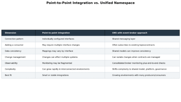
Figure 4. Comparison of point-to-point integration and a unified namespace with an event-broker approach.
The central trade-off is that a shared data layer reduces some forms of coupling while introducing a common platform and a shared set of data contracts that must themselves be governed. The complexity does not disappear; it moves away from a large collection of bilateral interfaces toward the design and operation of the shared information model.
This distinction matters because an inadequately designed UNS can become a bottleneck. If every new application requires extensive custom transformation logic, if the namespace is inconsistent between plants, or if the broker is operated without adequate monitoring and recovery procedures, the expected benefits may not materialize.
Manufacturers should therefore evaluate the architecture according to the actual pattern of information exchange, the rate at which new applications are introduced, the consistency of the existing data model, and the operational capabilities of the teams responsible for the platform.
8. Edge-to-Cloud Architecture for Automotive Manufacturing
An edge-to-cloud architecture allows manufacturers to combine local operational responsiveness with enterprise-wide access to production information. In this design, shop-floor equipment provides raw signals and events, edge components normalize and contextualize selected information, and the messaging layer distributes the resulting data to authorized consumers. Cloud or data-platform services can then support historical analysis, cross-site reporting, and advanced applications where appropriate.
A practical implementation may include the following layers:
- Shop-floor layer: PLCs, robots, sensors, machine vision systems, and industrial controllers generate signals and events.
- Connectivity and edge layer: Gateways and edge services connect legacy and modern equipment, translate protocols, validate data, and apply local processing where required.
- Unified data layer: A broker and namespace structure make operational information available through consistent topics and data contracts.
- Application layer: MES, quality systems, maintenance applications, dashboards, and analytics tools consume the information relevant to their functions.
- Enterprise and cloud layer: Selected data supports cross-site analytics, long-term storage, reporting, and cloud-based services under appropriate governance controls.
The boundaries between these layers are logical rather than necessarily physical. A manufacturer may operate brokers locally at each plant, use a central broker for selected enterprise data, or deploy a more distributed arrangement depending on network topology, resilience requirements, and security policy.
MQTT and Sparkplug are relevant technologies in this context, although their roles should be distinguished. MQTT defines a lightweight publish/subscribe messaging protocol. Sparkplug builds on MQTT with conventions intended to improve interoperability in industrial applications, including structured payloads and state-management behavior. Using Sparkplug can help establish more consistent industrial messaging, but it does not replace the need to define business entities, production-order relationships, product identity, or plant-specific governance.
Manufacturers should also avoid assuming that every factory must adopt the same physical architecture. A site with reliable connectivity and centralized platform operations may use a different distribution pattern from a facility with strict network segmentation or limited external connectivity. The more important requirement is that the chosen topology supports consistent data semantics, appropriate security boundaries, and reliable operation.
9. Measuring the Business Value of a Unified Namespace
The business case for a unified namespace should be evaluated through measurable changes in integration effort, data accessibility, and the delivery of digital manufacturing initiatives rather than through connectivity metrics alone. A system that publishes thousands of messages per second is not necessarily creating business value if the information cannot be interpreted reliably or used to improve a process.
One of the most relevant measures is the effort required to onboard an additional application or production asset. In a point-to-point environment, the introduction of a new consumer may require multiple interfaces and separate data mappings. With a well-governed shared layer, the consumer may be able to reuse existing topics and contracts, although adapters and transformations will still be necessary where its requirements differ from the established model.
Manufacturers can track several indicators to determine whether the architecture is delivering its intended benefits:
- Integration effort per new system: Engineering hours required to connect, validate, and deploy an additional application.
- Time to onboard an asset or production line: The elapsed time between confirming integration requirements and making reliable data available to consumers.
- Interface maintenance effort: Time spent diagnosing failures, modifying mappings, and coordinating changes across connected systems.
- Data availability and quality: The proportion of required data that is accessible, valid, sufficiently current, and associated with the correct production context.
- Reuse of existing data contracts: The extent to which new applications consume established topics and schemas rather than creating new bespoke interfaces.
- Time to deliver digital use cases: The time required to introduce capabilities such as production monitoring, quality analysis, or maintenance analytics.
- Operational reliability: Message-processing health, recovery time, data gaps, and the availability of critical data services.
These indicators should be measured before and after implementation, using comparable workloads and clearly defined measurement periods. Otherwise, improvements may be attributed to the UNS when they actually result from other changes, such as equipment upgrades, application replacement, or process redesign.
The economic benefit is best understood in terms of marginal integration cost. A shared architecture may require a meaningful initial investment in the namespace, adapters, governance, security, and platform operations, but the expected value comes from making future integrations more repeatable. As more systems reuse the same data contracts, the organization may reduce duplicated development and shorten delivery cycles for subsequent projects.
This outcome is not automatic. A UNS that requires extensive customization for every new consumer may deliver limited savings, while a carefully governed implementation can establish reusable patterns that become more valuable as the number of applications and sites increases.
10. A Practical Implementation Roadmap
Manufacturers should avoid treating a UNS initiative as a plant-wide infrastructure replacement that must be completed before any business benefit can be demonstrated. A phased approach allows teams to validate the architecture against a specific operational problem, establish reusable foundations, and expand only when the initial implementation proves reliable.
Phase 1: Assess the existing integration landscape
Document the systems, interfaces, data flows, and ownership arrangements that currently support the selected manufacturing process. Identify where the same information is mapped repeatedly, where application dependencies make changes difficult, and which data gaps limit planned digital initiatives. Include network segmentation, legacy protocols, availability requirements, cybersecurity policies, and team responsibilities.
Phase 2: Select a use case with measurable value
Choose an initial use case that requires information from multiple systems and has a clear operational objective. Production-state visibility, downtime analysis, quality-event correlation, and asset monitoring can provide useful starting points when the relevant data is available. Establish baseline measurements for integration effort, data quality, and delivery time before implementation begins.
Phase 3: Define the canonical model and namespace
Agree on identifiers, topic conventions, payload schemas, and data-quality rules. Define how assets, orders, parts, and events relate to one another, and identify the authoritative source for each important data domain. Develop the model collaboratively across manufacturing engineering, operations, IT, and application owners.
Phase 4: Implement connectivity and the messaging layer
Connect the selected data sources through suitable gateways, adapters, or application interfaces, then publish the required information through the chosen messaging infrastructure. Introduce validation, access control, monitoring, and recovery behavior from the outset, and test network interruptions, consumer restarts, duplicate messages, and schema changes.
Phase 5: Integrate consumers and validate reuse
Connect the initial applications, then introduce a second consumer or use case to test whether the model can be reused without duplicating the original integration logic. If every consumer requires extensive custom transformation, revisit the data contract before expanding.
Phase 6: Expand through governance and continuous improvement
Expand the namespace to additional assets, systems, and production lines using lessons from the pilot. Establish processes for approving schema changes, reviewing access permissions, monitoring data quality, retiring obsolete topics, and maintaining documentation. Scale according to demonstrated reuse and business demand rather than the number of connected devices alone.
Conclusion: From Connected Systems to Scalable Manufacturing Intelligence
Automotive manufacturers do not necessarily lack production data; the greater challenge is making that data accessible, consistent, and reusable across the systems responsible for operating and improving the factory. As digital initiatives expand, the cost of maintaining bespoke interfaces can become a constraint on how quickly manufacturers can deploy new capabilities, from production monitoring and quality analytics to predictive maintenance and AI-driven optimization.
A well-designed Unified Namespace (UNS) can help address this challenge by establishing a shared information structure through which manufacturing systems publish and consume operational data. When supported by a consistent manufacturing data model, a secure edge-to-cloud architecture, and robust data governance, this approach can reduce unnecessary integration dependencies and create a more scalable foundation for future digital initiatives.
Turning this architecture into measurable operational value, however, requires more than selecting the right technology. Manufacturers must also integrate legacy equipment, align data across operational and enterprise systems, modernize existing applications where necessary, and ensure that new solutions meet their production requirements. This is where the combination of industrial understanding and software engineering expertise becomes essential.
At NTQ Europe, we help manufacturing and automotive businesses address these challenges through custom software development and system integration, AI and data solutions, cloud services, application modernization, and technology consulting. By connecting industrial systems with scalable digital solutions, we help businesses build a more reliable data foundation for operational visibility, smarter decision-making, and continuous improvement.
Planning to build a more connected and data-driven manufacturing environment? Talk to NTQ Europe about your current integration challenges and digital manufacturing priorities. Our team can help you assess your existing architecture, identify opportunities for improvement, and define a practical roadmap toward a more scalable manufacturing data ecosystem.
Talk to us: https://ntq-europe.com/
Read latest article: HiL vs SiL: Where Should Automotive Teams Invest First?